Arduino I2C controller for the TI DLPC350
In the last week I have been programming an Arduino Nano ESP32 to control a DLP projector over the I2C protocol. I post here some notes on this ongoing work.
Premises
The projector is the Wintech PRO4500 we use at SAMBA Lab for the grayscale photolithography of soft active materials such as polymer gels (as described e.g. in (Boiardi & Noselli, 2024)). This device is based on Texas Instrument’s DLP LightCrafter 4500 that utilizes the DLP4500 WXGA DMD (digital micromirror array) and Texas Instrument’s DLPC350 controller.
The technical documentation from TI suggests two ways to interface with the projector: I2C and USB; I opted for I2C for simplicity, also considering that my project does not have high bandwidth requirements.
The DLPC350 operates at 3.3V, as stated here, therefore the I2C connected needs to be driven with a 3.3V signal. For this reason, the Arduino Nano ESP32 was selected as a controller, as it natively operates at 3.3V.
The I2C protocol
The source for this section is a document from Texas Instruments, which contains way more detail that needed for my project.
I2C (Inter-Integrated Circuit) is a two-wire serial communication protocol using a serial data line (SDA) and a serial clock line (SCL). Multiple controllers and target devices can be simultaneously connected on the same I2C bus. Each target node is identified by a unique 7 bit address.
The SCL line is primarily controlled by the controller device and is used to synchronously data on the network; multiple clock speeds are supported. The serial data line SDA is used to transmit data to or from target devices. At a given time only one device can be transmitting data on the I2C bus.
To avoid contention of the line, I2C communication is initiated from the controller device with an I2C START condition. To do this, the controller device first pulls the SDA low and then pulls the SCL low. This sequence indicates that the controller device is claiming the I2C bus for communication, forcing other controller devices on the bus to hold their communication. When the controller device has completed communication, the SCL releases high and then the SDA releases high. This indicates an I2C STOP condition.

After the communication has been initiated, a sequence of ones and zeros for serial communication. SDA is used for the data bits while SCL is the serial clock that times the bit sequence. A logical one is sent when the SDA releases the line, allowing the pullup resistor to pull the line to a high level. A logical zero is sent when SDA pulls down on the line, setting a low level near ground.
The ones and zeros are received when SCL is pulsed. For a valid bit, SDA does not change between a rising edge and the falling edge of SCL for that bit. Changes of the SDA between the rising and falling edges of the SCL can be interpreted as a START or STOP condition on the I2C bus.
The first data sent is the 7bit address of the target node, and the 8th bit of the first frame is used to indicate the mode. If this bit is 1, the controller is asking to read data from the target device. If this bit is 0, the controller asks to write data to the target device.
After any communication byte, an extra 9th bit is used to verify the communication was successful. The target device pulls down the SDA during the SCL pulse to indicate to the controller that the address was received. This is known as an acknowledge (ACK) bit. If this bit is high, then no target device received the address and the communication was unsuccessful.
All subsequent data is sent one byte at a time in data frames separated by ACK bits.
Step 1: Testing the I2C signal
While writing the code for the Arduino, I wanted to test the I2C signal, before connecting it to the projector. The testing was done with a second Arduino, acting as a target node as the projector, and reading the signal from with an oscilloscope (R&S®HMO1002).
First messages through I2C
Let us try to send a 0x00 byte over the I2C protocol, here is the code
#include <Arduino.h>
#include <Wire.h>

#define I2C_ADDRESS 0x1A

void setup() {
  Wire.begin(); // I2C0
}

void loop() {
  Wire.beginTransmission(I2C_ADDRESS); //begin transmit to device 0x1A
  Wire.write(0x00); //send data
  Wire.endTransmission(); //stop transmit
  delay(100);
}
The message can be read from a reader arduino programmed with the following code:
#include <Arduino.h>
#include <Wire.h>

#define I2C_ADDRESS 0x1A

void wireEvent(int howMany) {
  Serial.print("Received on I2C: ");
  while (Wire.available()) {
    byte c = Wire.read(); // receive byte as a character
	Serial.print(c, HEX);
	Serial.println("");
  }
}

void setup() {
	Serial.begin(9600);

	// Initialize I2C communication
	Serial.println("Initializing I2C communication...");
	Wire.begin(I2C_ADDRESS);
	Wire.onReceive(wireEvent);
}

void loop() {

}
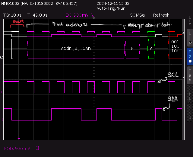
But measuring the signal with the oscilloscope, we just detected the beginning of the transaction, and no message is sent:
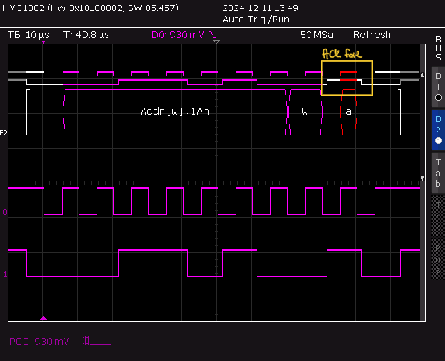
0x1A on the bus. 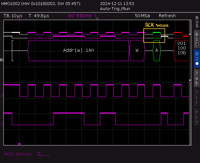
0x1A on the bus. This is because, without the acknowledgement from the target node, the controller does not send the message.
Connecting both oscilloscope and reader node to the controller, we can indeed read the message with the arduino and see the right signal on the oscilloscope

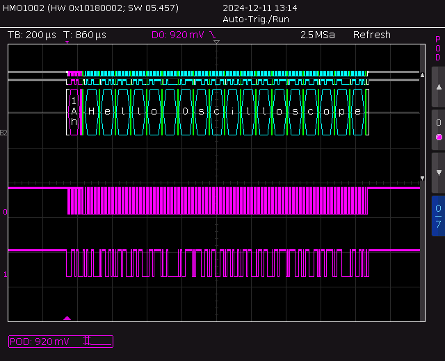
In the above picture, the data sent by the controller node is Wire.write("Hello Oscilloscope"); and the oscilloscope is decoding the signal in ASCII instead of HEX.
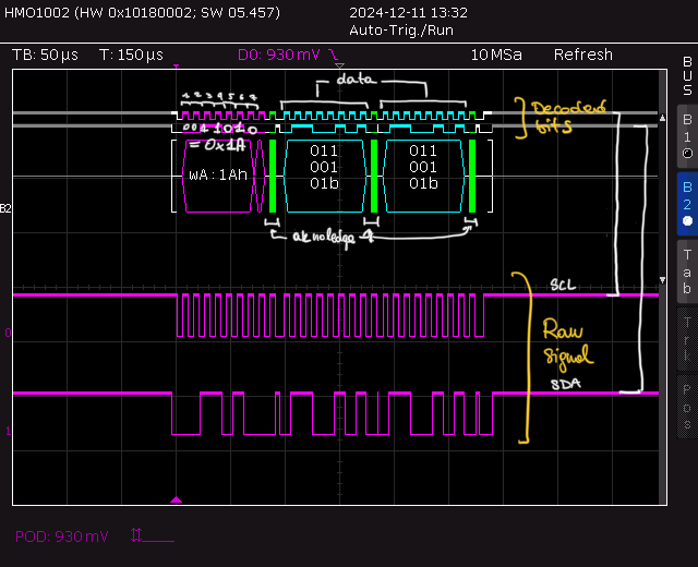
On the structure of I2C transactions
The structure of I2C transactions is reported in the left figure below; in this section I will compare this structure with the traces measured with the oscilloscope. For more details (still practical) on I2C protocol read here.

Step 2: Addressing a specific register subaddress
To get or set the state of the projector, I need to read or write (respectively) specific registers of its controller, as stated in the programmer’s guide. Each register address requires a certain number of data bytes, typically four. Thus, a register address is followed by variable length data. These bytes contain the value read or written into this register, with the most significant byte first.
To move the read/write pointer head head to the correct address, the transaction stars with a write containing the register sub-address. The subaddress also contains a read/write bit in the most significant bit position. For read functions, bit 7 is set to 0. For write functions, bit 7 is set to 1.
Therefore, each transaction (even those only comprising reading a register) starts in write mode, in order to send the subaddress to the target node. After START, 7bit address, and a 0bit for write mode, the subaddress byte is sent, pointing to the register containing the command of the desired DLPC350 function.
If the controller wants to write on the selected register, the transaction proceeds with other data frames containing the data to be written. If in the other hand, the transaction is a read, the controller needs to send another I2C START condition followed by the target address with the I2C read/write bit set to 1.
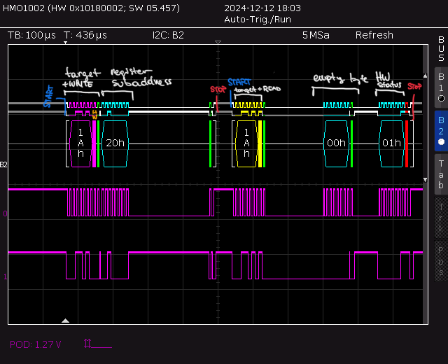
Read: Get projector hardware status
Let us try to read the byte at address 0x20, containing the hardware status of the projector, as stated in the table below. Looking at the trace from the oscilloscope, we can confirm that the projector initialized successfully and no error is detected.
  // Move reding pointer to register 0x20
  Wire.beginTransmission(I2C_ADDRESS); // begin transmit to device 1
  Wire.write(0x20); // send register address
  Wire.endTransmission(); // end writing without sending stop bit

  // Read 2 bytes from register 0x20
  Wire.requestFrom(I2C_ADDRESS, 2); // request 1 byte from slave device

Write: Turning the LED on and off
Finally we are at the point where we can turn the LED of the projector on and off, which is was essentially the first goal (we’ll see if we need more granular control for future photolithographic techniques).
This is done by changing the content of register 0x10, which contains the status od thre RBG LEDs. Actually our projector only has a blue LED, so the relevant bit to flip to turn it on and of is bit 2 of the register.
Wire.beginTransmission(I2C_ADDRESS); // begin transmit to device 1
Wire.write(0x90); // register 0x10 with bit 7 set to 1 for write mode
Wire.write(0x04); // turn on blue led
// Wire.write(0x00); // turn off blue led
Wire.endTransmission(); // end writing without sending stop bit
We can also change the intensity of the light by setting the PWM duty cycle of the LED power supply by setting the 3 LED Driver Current Control bytes at register 0x4B.
Setting the image
For the moment, the images to be projected are sent thought HDMI, but for the future I might need to look into individually addressing each micromirror to dynamically change the projected patterns.
References
2024

Enjoy Reading This Article?
Here are some more articles you might like to read next: